Introduction
In Part 1, I outlined what we’re building, and the first steps in turning this into something real - picking the major components. These include:
- The microcontroller, which will run the actual code shuffling bytes from an audio source out the Ethernet port
- The ethernet PHY, which interfaces the MCU with the physical RJ45 jack
- The microphone itself, which provides an I2S interface to the MCU
- The PoE power supply, which negogiates for power delivery from the PoE switch in my basement
So far we have one of these components picked out:
| Role | Component | Datasheet |
|---|---|---|
| MCU | Microchip ATSAME53J19A | Datasheet |
| PHY | ? | ? |
| Mic | ? | ? |
| PoE | ? | ? |
Let’s dig into PHY selection first.
Component selection - Ethernet PHY
It’s common for an IC that supports ethernet to have a built-in MAC, but not a PHY. That is - it knows how to speak Ethernet Layer 2 but it doesn’t know how to actually translate that into voltages and timings running across the twisted pair (e.g. Cat5, Cat6) “ethernet cable” that we are all familiar with.
This makes sense to separate out - twisted pair is not the only way that we transmit Ethernet frames (even though the idea of using fiber to send the 100Mbps that this MCU is capable of is hilariously unlikely to happen in practice).
In any case - there is a standard interface from MACs to PHYs called Media-Independent Interface or MII. This is an 18-line interface, though there is a “reduced” version (called, shockingly, RMII) which uses half as many lines at twice the clock. Going back to our MCU’s datasheet linked above, and searching for ‘RMII’ shows that our MCU supports it. Generally when we have an option for a smaller number of wires to run, it’s always a win for ease of PCB design, so let’s make sure that we pick a PHY that supports RMII as well.
For this I’m not sure which vendor I should start with, so I’ll actually start with Digikey directly. I don’t know what sub-category this is in, but I’ll throw ‘RMII’ into the search box as I know it’s something we need to support. That indicates to me that the ‘Drivers, Receivers, Tranceivers’ category might be what I want, which sounds right. When I add the standard “Product Status -> Active” and “In Stock” filters, I get to 5,582 results in this category. But adding in “MII, RMII” and “RMII” as supported in the “Protocol” field, and we’re now down to 18:
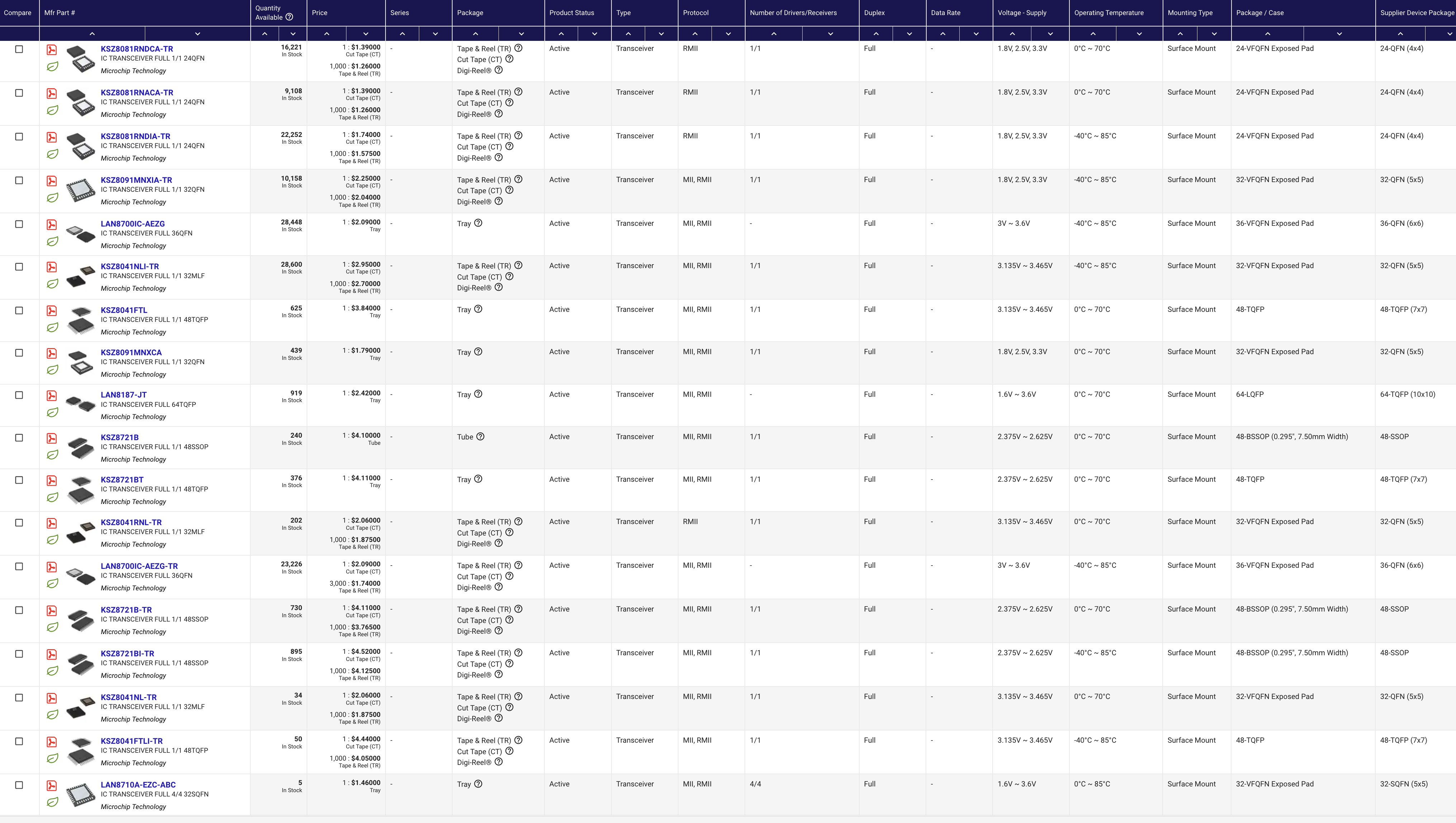
Notably, these are all from Microchip. There’s no need at all that these need to be from the same vendor as the MCU - but, it can be handy. Datasheet conventions like the names of certain signals might be consistent between the two, and it’s possible the PHY datasheet might even reference a Microchip MCU in an example configuration, which would be super handy.
Filtering for only 1 driver rather than 4 takes a few more parts off the list, and we’re now down to 14, which is still a tough choice. I’ll further filter by package - a 7x7mm, 48-pin QFP will be easier to work with than a tiny 4x4mm QFN. That takes it down to 3: the KSZ8721BT, and two variants of the KSZ8041FTL.
Checking out the Microchip pages for the KSZ8721 and the KSZ8041, it looks like the 8721 is a 2.5v part, which is a bit weird, and looks like it’s meant for some specific applications that ‘know who they are’. However, the 8041 looks totally ‘normal’. And looking at the datasheet, the only difference betweeen the “KSZ8041FTL-TR” and “KSZ8041FTLI” is whether they come in a tape+reel or tray packing configuration, which doesn’t matter to us if we’re just ordering one and hand-placing it. The KSZ8041FTL is 60 cents cheaper per part, so let’s call it - the Microchip KSZ8041FTL is our ethernet PHY.
| Role | Component | Datasheet |
|---|---|---|
| MCU | Microchip ATSAME53J19A | Datasheet |
| PHY | Microchip KSZ8041FTL | Datasheet |
| Mic | ? | ? |
| PoE | ? | ? |
MEMS Microphone selection
I started this with just a Google search for “i2s mems microphone”, which lead me first to this Adafruit link which itself contains a part number, SPH0645LM4H. Plugging this into Digikey gets one hit, and there are gazillions in stock. Clicking through to the datasheet, this looks like just the right thing - we’re building “connected equipment” after all!
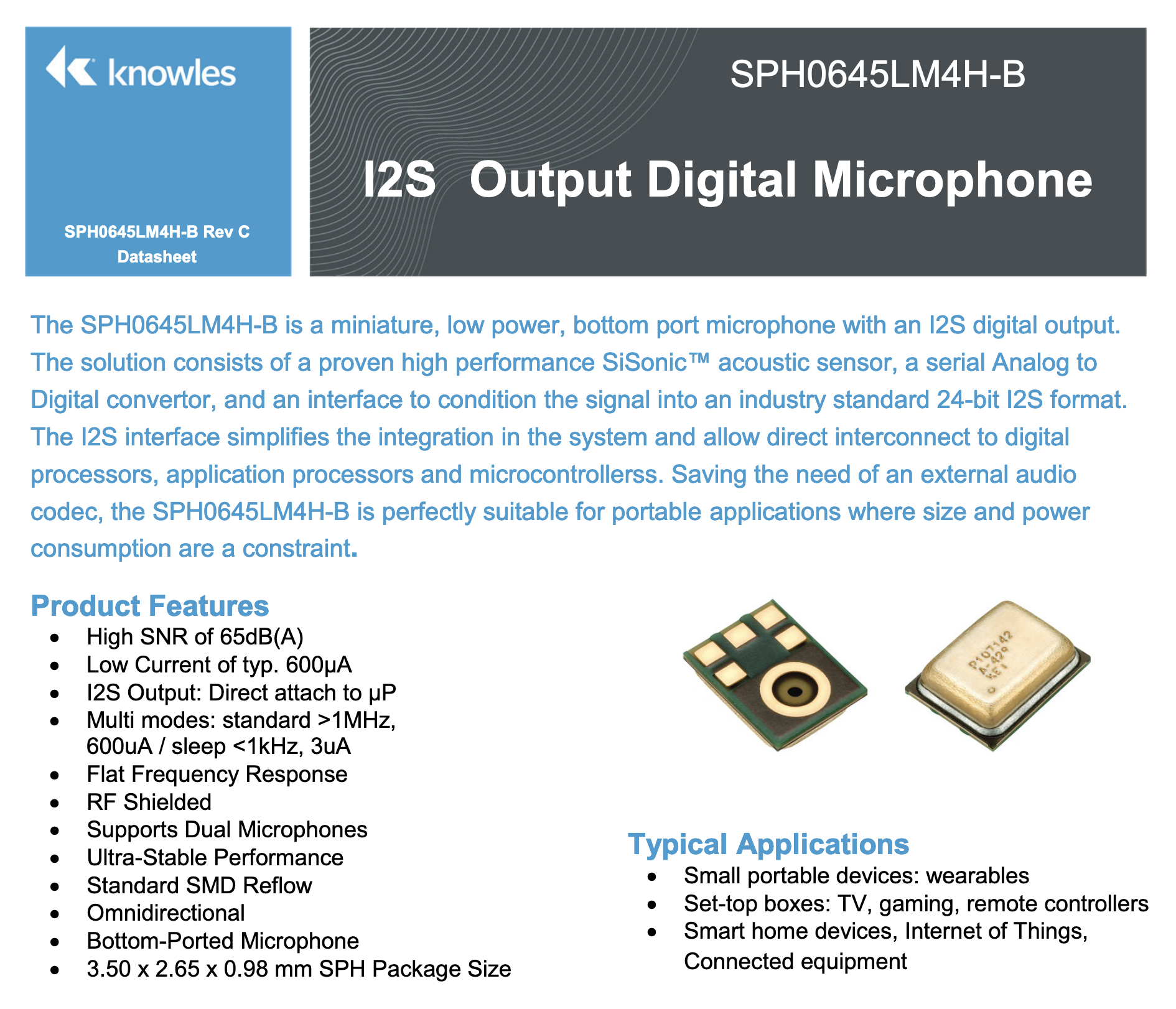
So - seems like a no brainer, and it’s great that we have an Adafruit breakout board for it that we can get a reference schematic and layout from to check our own work against. Adding it to the list:
| Role | Component | Datasheet |
|---|---|---|
| MCU | Microchip ATSAME53J19A | Datasheet |
| PHY | Microchip KSZ8041FTL | Datasheet |
| Mic | Knowles SPH0645LM4H | Datasheet |
| PoE | ? | ? |
Last up is the PoE controller, which will certainly not be as easy as that.
PoE controller
The wikipedia page for PoE is worth a read, specifically this table on the negotiation sequence:
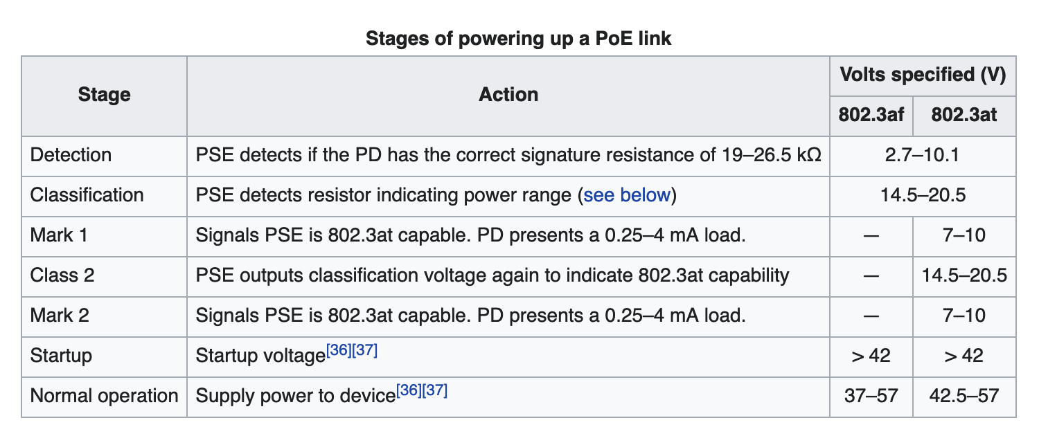
In a nutshell - the PSE (Power Sourcing Equipment) runs the device that wants power through a set of tests, first by looking for a couple of special resistor values. For higher-powered PoE devices that make use of the 802.3at or 802.3bt standards there are additional parts to the negotiation, but it’s still something you want an IC to orchestrate for you - even with the relatively simple, lowest-tier 802.3af standard. 802.3af is more than enough power for us anyway - it delivers almost 13 Watts, when our MCU might consume maybe half a watt at most.
Similarly to when looking for a PHY, I type “802.3af” into the digikey search and see that there is a dedicated category for Power Over Ethernet (PoE) Controllers. Adding some filters:
- Type => ‘Controller (PD)’ or ‘Controller (PD), DC/DC’ since we are a Powered Device (PD) not Power Sourcing Equipment (PSE)
- Product Status => ‘In Stock’
- Number of Channels => ‘1’
- Stocking Options => ‘In Stock’
Takes us to 103 results.
I actually want to filter out all of the ones that support higher levels of PoE - those are probably more expensive and more complex. If there’s a solid one that only does 802.3af, that would be great. That takes us to 51, and then filtering out support for Auxiliary Sense (supporting a non-PoE power source) and the associated “Controller (PD), DC/DC” ‘Type’, get us to 26. Filtering by the easiest packages to deal with - 8 pins, skipping PowerSOIC and WFDFN (which will each have an exposed ground pad that will be mildly annoying to make a solder footprint for), and we’re down to 16 devices, 11 from Texas Instruments and 5 from Analog Devices.
I see that a few are “0 in stock” but with a bunch on the “marketplace”, and that sounds like a recipe for annoying shipping, so I hit “Marketplace Product => Exclude” and now we’re at 7:
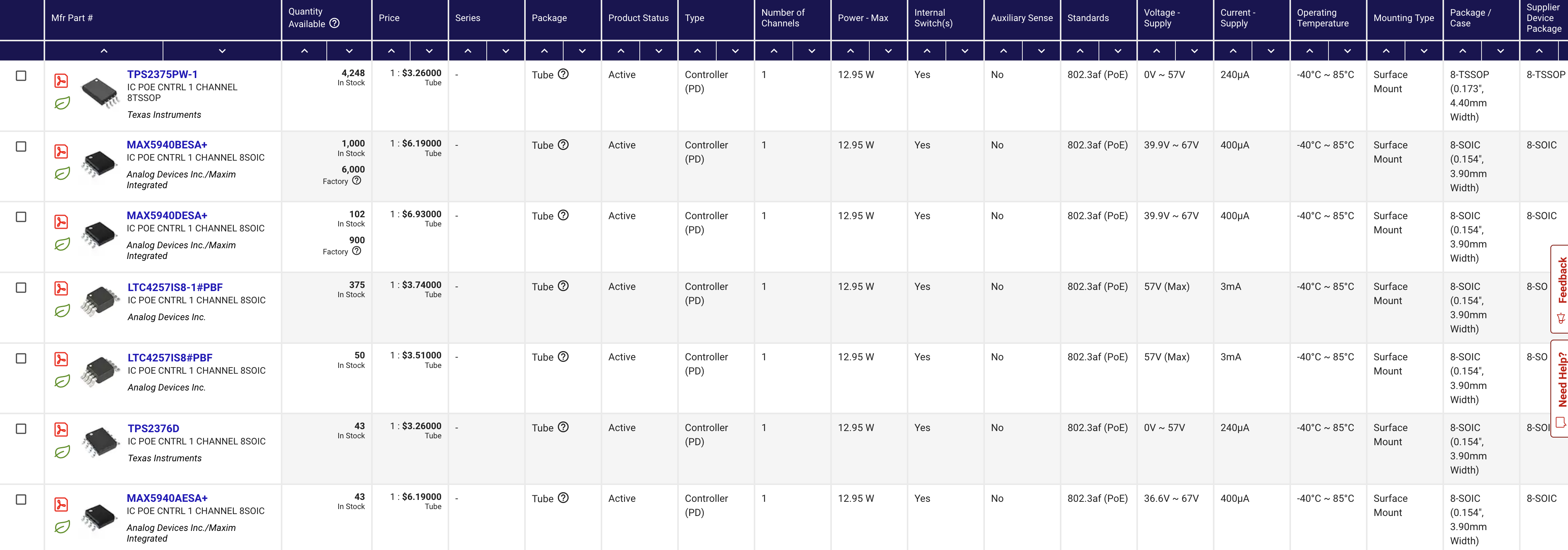
It’s actually just 4 - if you look through the MAX5940 Datasheet you see that the AESA, DESA, and BESA are basically the same. From the TPS2375 Datasheet the TPS2375 has a fixed UVLO (undervoltage lockout) and an unused pin 7, but the TPS2376 has an adjustable one that would require 2 more passives to make a resistor divider on pin 7 - no thanks. Down to the TPS2375, MAX5940, or LTC4257.
The MAX5940 is inexplicably twice as much per part, so let’s rule that out. I don’t doubt that there’s some reason, but I also have no reason to believe the other parts wouldn’t work. This is a pretty tried-and-tested protocol. Between the remaining two, I think I’m going to go with the TI, for two soft reasons:
- It’s very marginally cheaper.
- I like the datasheet more. Particularly the detailed application diagram right on the first page, with values for passives and suggested part numbers for the diode bridges. That’s something I’m going to be able to turn into a board schematic in a pretty 1:1 way, which will reduce the chances I make a mistake.
So - there we are! The Texas Instruments TPS2375 is our choice for our last major component we need for this project.
| Role | Component | Datasheet |
|---|---|---|
| MCU | Microchip ATSAME53J19A | Datasheet |
| PHY | Microchip KSZ8041FTL | Datasheet |
| Mic | Knowles SPH0645LM4H | Datasheet |
| PoE | Texas Instruments TPS2375 | Datasheet |
Next Steps

We’re starting to get our arms around this. But these are still 4 generally unfamiliar parts at least to me - I know myself well enough to say that this is guaranteed not to work on the very first board revision, and if I’m failing to get my MCU up, I might be wasting other ICs on boards that have more fundamental problems.
So my approach here is usually to start with breakout and test boards, with minimal components. Small boards have faster turnarounds both in design and fabrication (cheaper to pay for expedited service - and may only need 2 layers).
In Part 3 I will be detailing how I might choose what order to tackle prototype boards for these ICs in, how I walk through datasheets, and the schematic phase of the first breakout board.