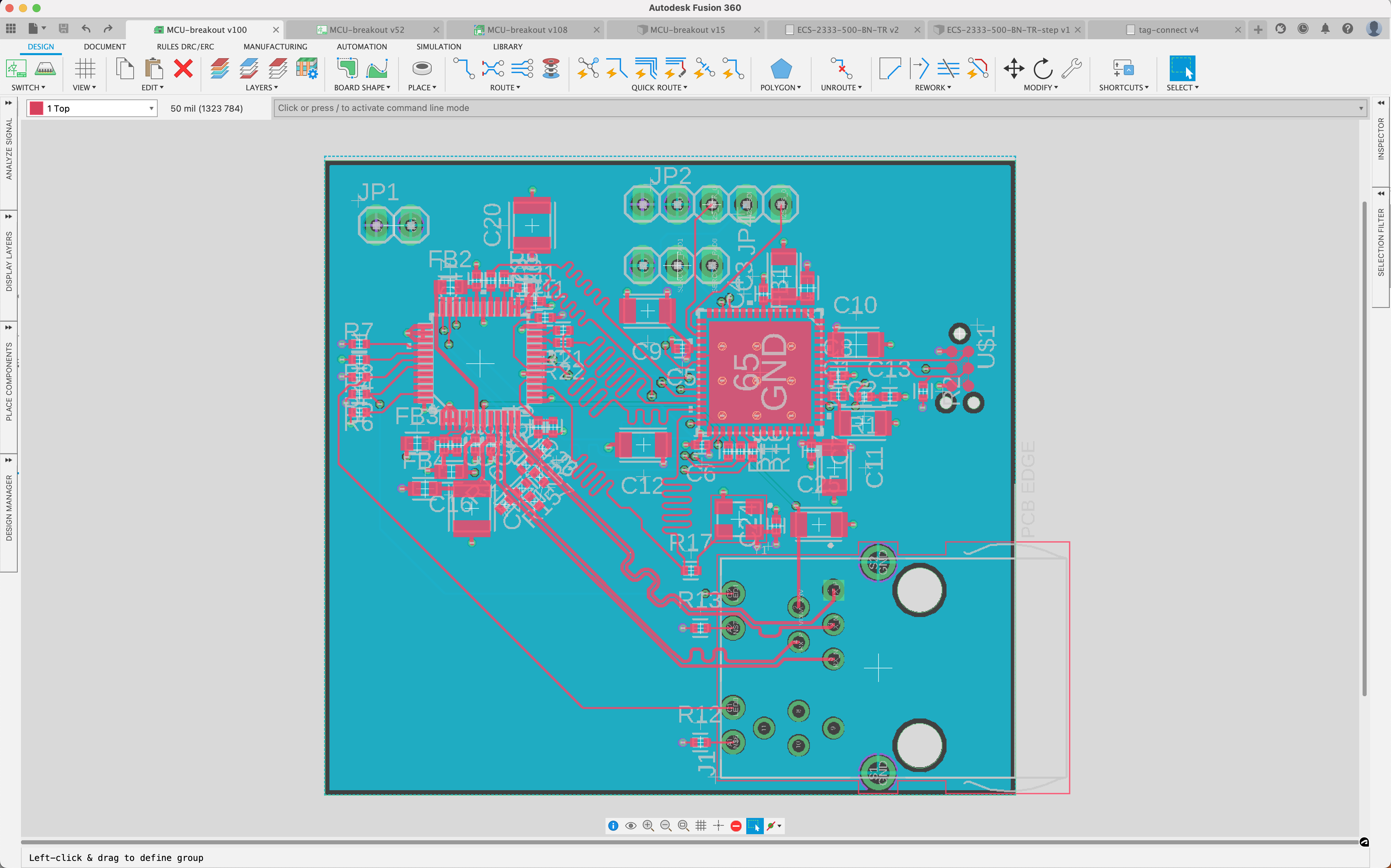
As I sit down again to work on more PCB layout, this is where we left things:
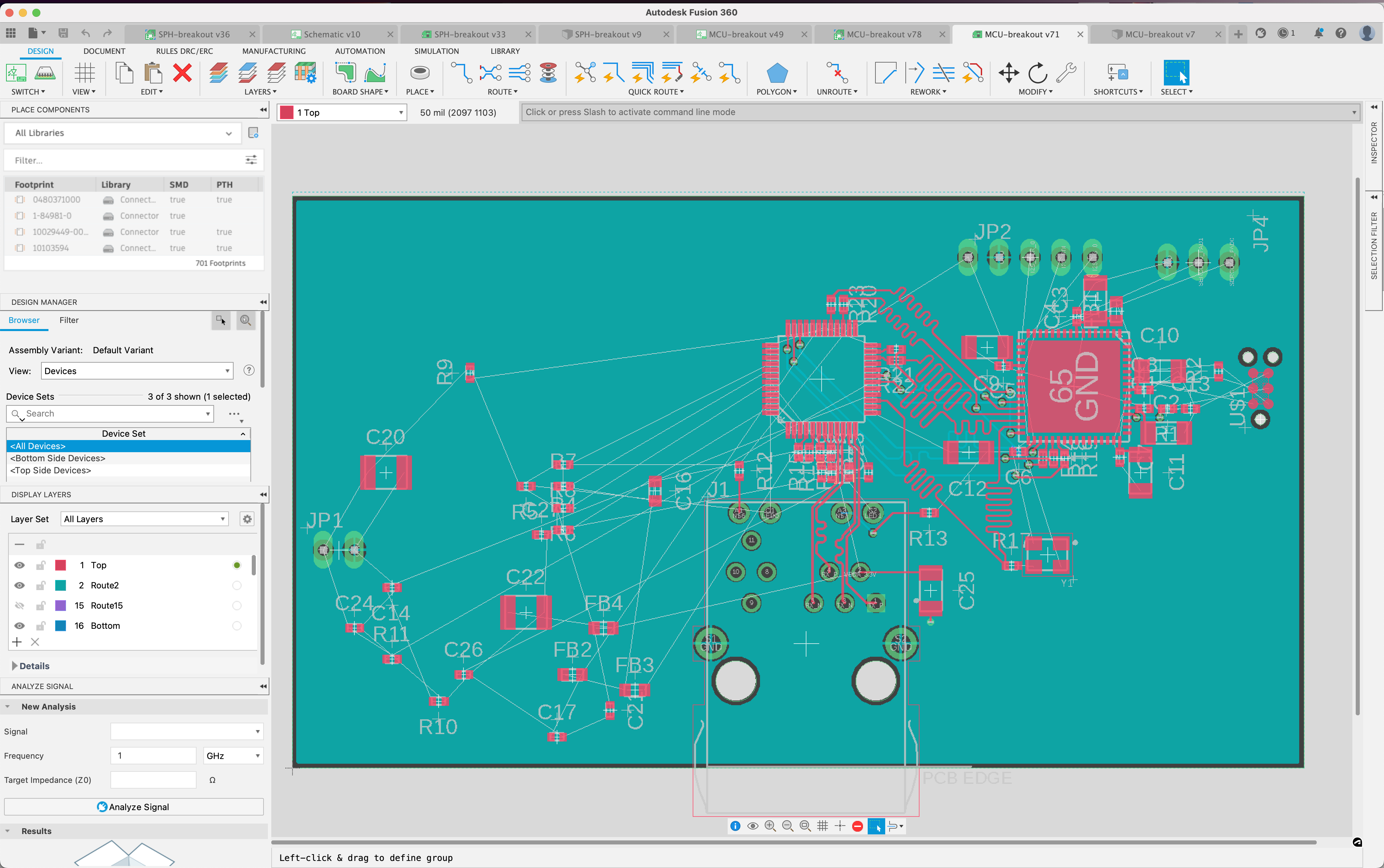
…I feel like I was further along. Anyway - I’m just going to go through piece by piece.
Random Components
R4, R5, R6, R7, R8, R9, and R11 are all either pull-up or pull-down resistors, which means thankfully they have no need to be near the IC at all. R10 and C14 form a calibration circuit on the REXT pin on the PHY.
After then moving the ferrite beads over to the analog nets, and the remaining decoupling capacitors over, I’m able to cut off half the board, but things are actually much too cramped on the south side of the PHY - there are a lot of components there that there’s no way I’ll be able to get traces to.
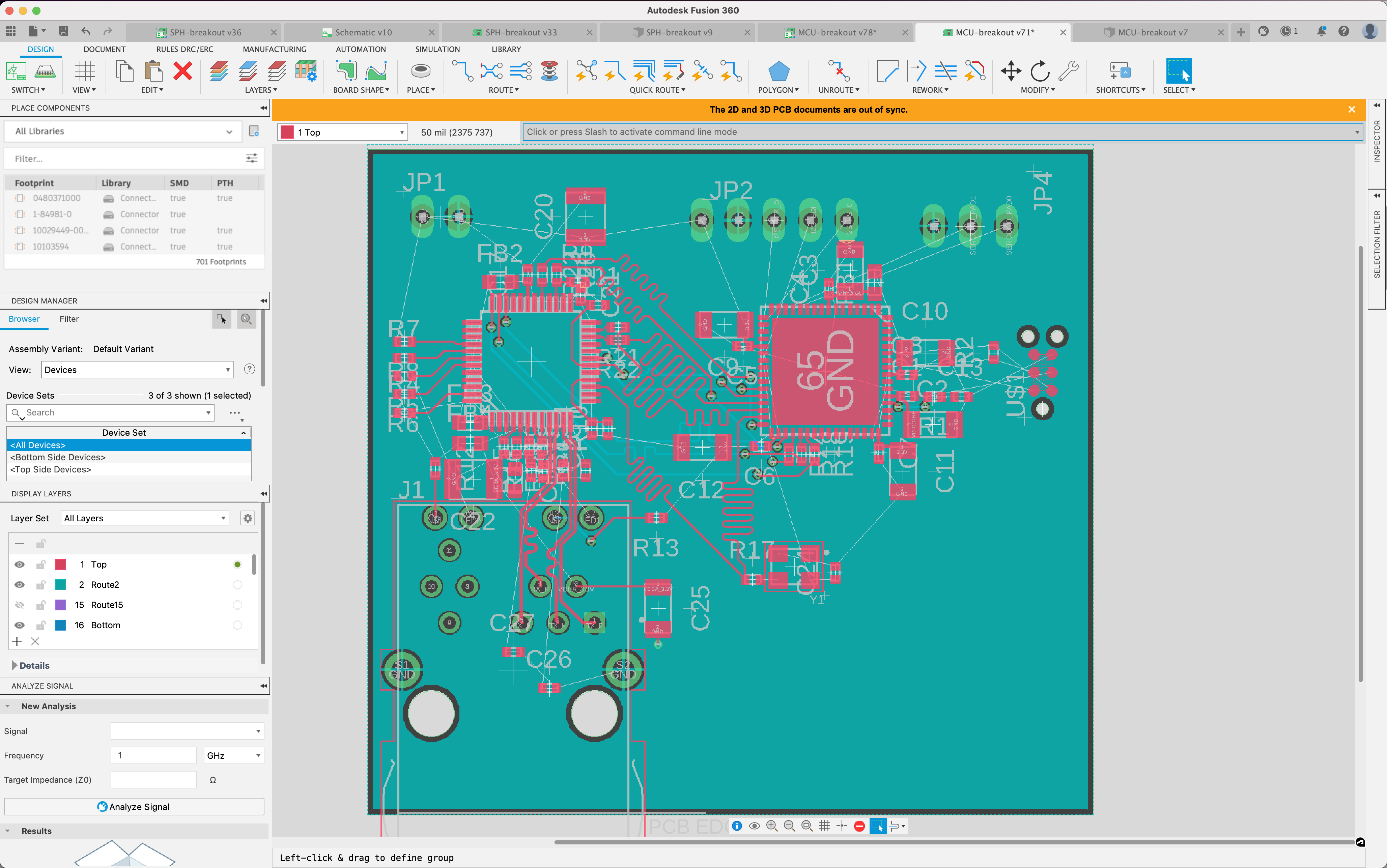
I’m actually going to pick up the RJ45 jack and put it in the bottom right part of the board, which will give me some more room to do things like attach the extra passive components the differential pairs need.
After this it’s a pretty tedius process of counting down the remaining airwires (i.e. logical connections not yet physically connected). Lots of them are really easy - just a quick via over to the 2nd layer (which is a uniform GND signal across the PCB) or to the 3rd layer (which is a uniform 3.3v layer across the PCB). After an hour or so spent on this…I’ve got every airwire connected, but there are some things I don’t love:
In particular, I really hate the passives attached to the analog differential pairs going to the jack. Something wonky here could really break it. I’m referring to just this part of the schematic, where it’s more visible:
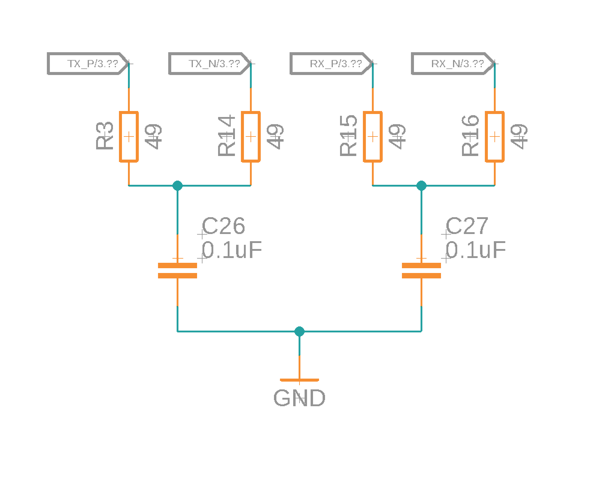
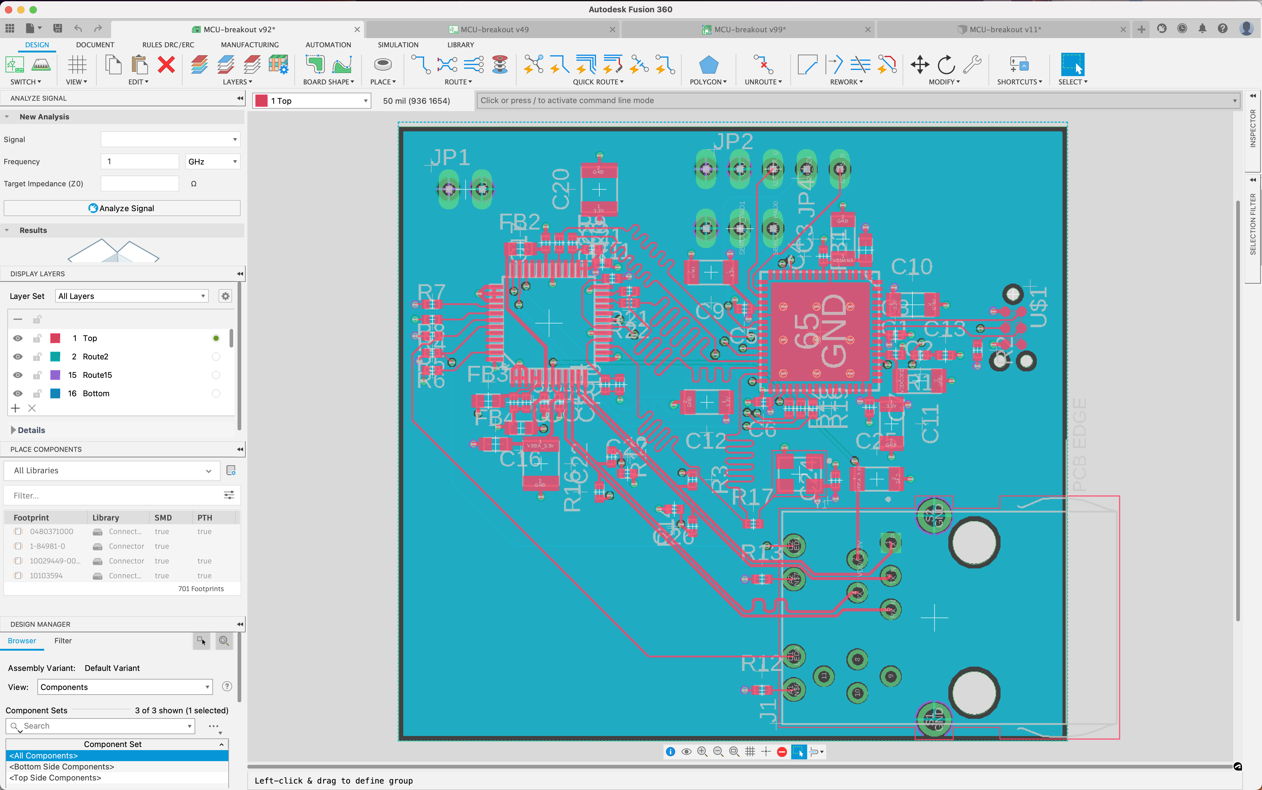
I did another pass moving them closer to the PHY (found an app note that recommended this), and angling them so they can just have the trace run past the pad rather than making a trace intersection. Also re-length-matched the differential pairs and matched the TX pair to the RX pair:
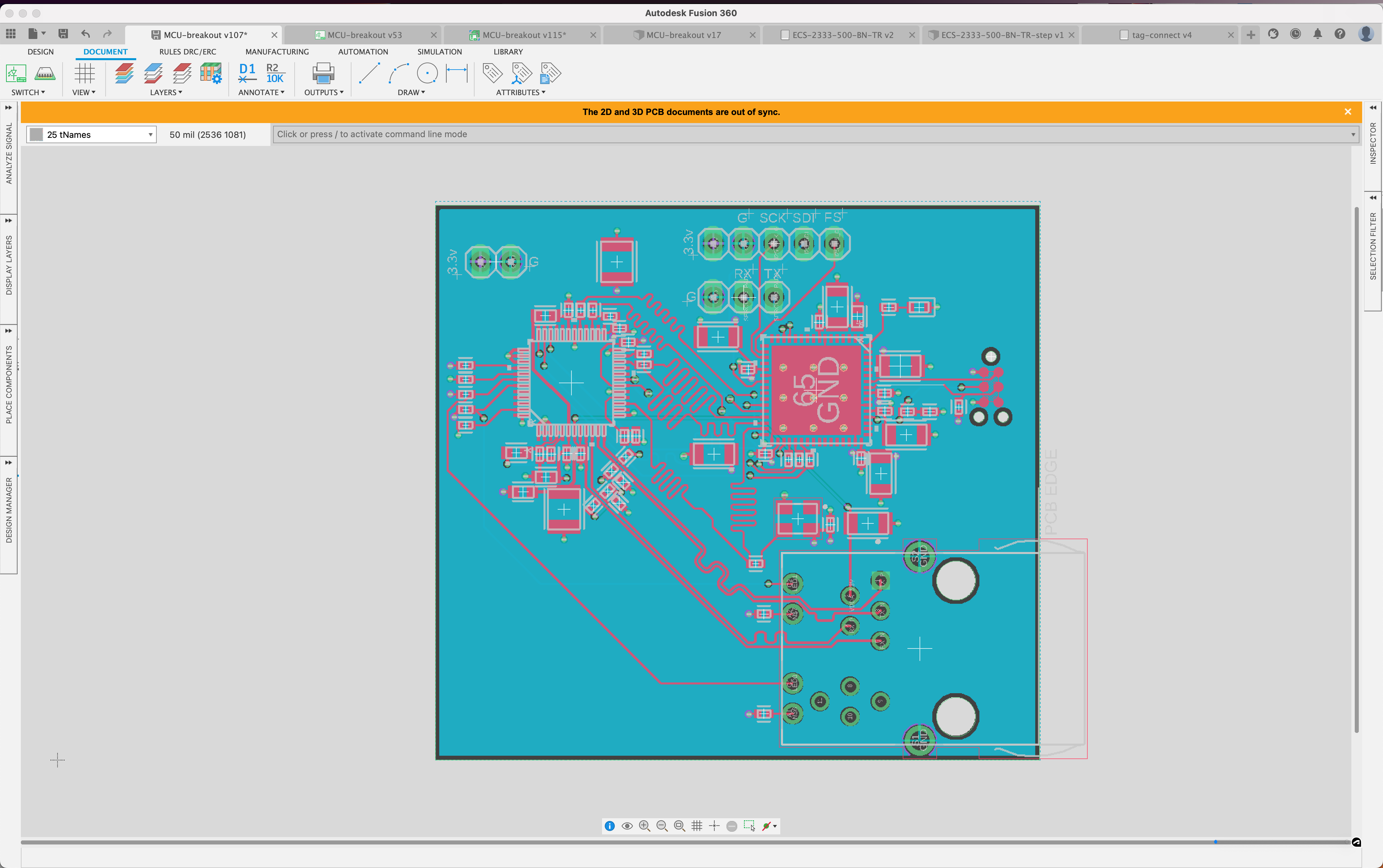
I’m also going to add a LED hanging off a random I/O port on the MCU that we can do a ‘sign of life’ blinky from. Pin 64 is wide open, so I’ll put one there. I also cleaned up all of the silkscren - the component names make it much too crowded - and added some extra to indicate alignment of the pin headers:
Now I start a close walkthrough of the board - making sure I’ve got through both checklists. I find:
- I never actually hooked up anything but a pull-down resistor to the RESET pin on the PHY.
- I’ve messed up the RESET pin on the MCU. PGM_RESET is meant to come from the programmer, with the circuit in between that and the MCU, but I have PGM_RESET also wired right into the MCU (and a RESET net going nowhere). Whoops.
- Actually, looking at it more closely, it’s not clear how the RESET pin is supposed to work when also using a programmer. I think I’m actually meant to connect the programming RESET net right into the MCU’s RESET pin. It’s actually a little simpler than I had it, since I don’t need to debounce a physical reset button.
- The MAC has a suggested reset circuit with a 10k pullup and a 10uF capacitor to ground. Added.
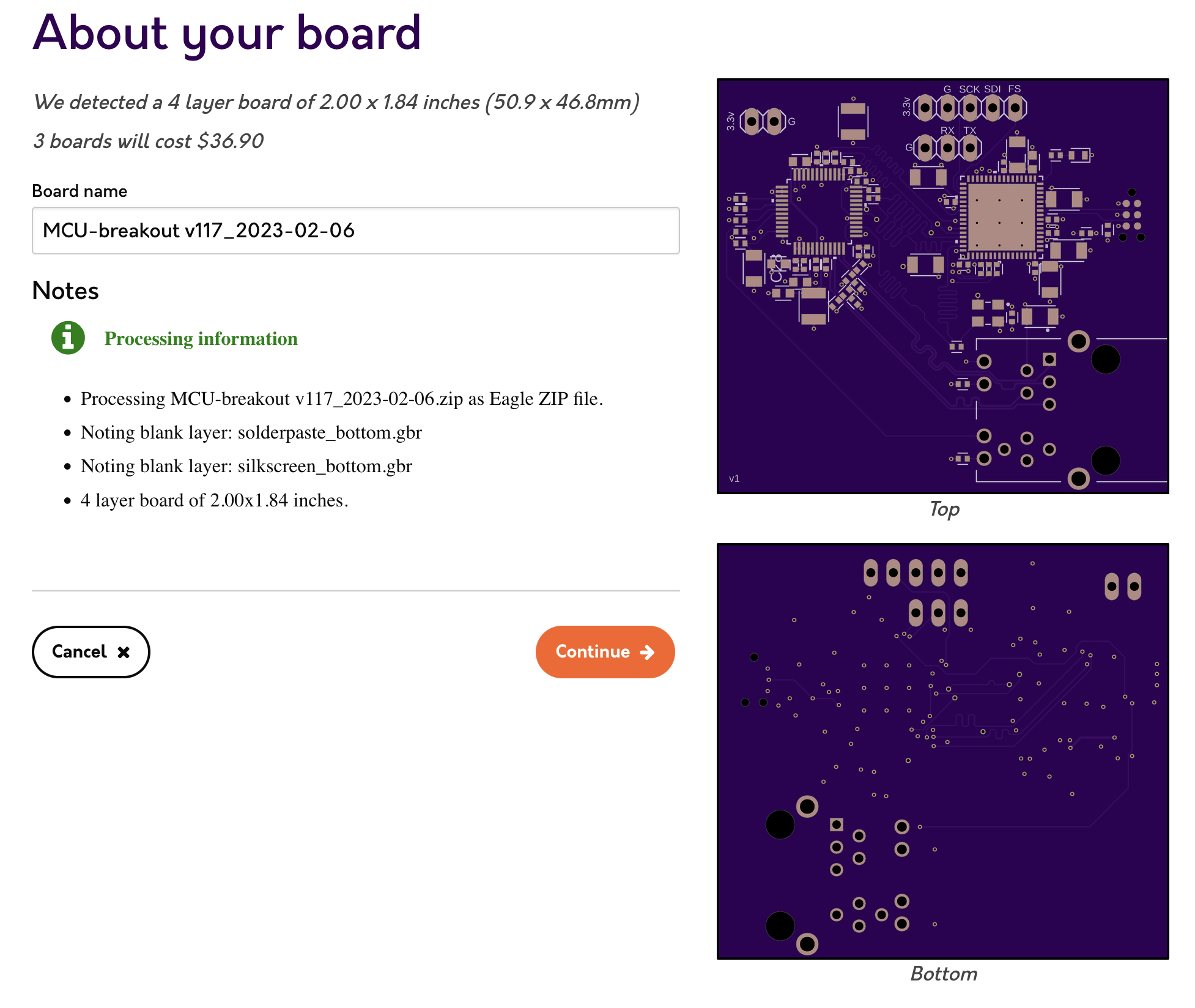
With those - as terrifying as it is, I think I’m ready to order the boards and stencil.
$36.90 from OSHPark:
And $21.32 for the stencil.
Now - on to a part order. We need a bunch here since we decided to shrink down all of the passives - I don’t have any 0402 resistors in my workbench. Luckily, passives are all cheap. The order is likely to be dominated by the MCU, PHY, and MagJack.
$60.90 from Digikey, and then another $15.96 from Mouser since the MCU was actually no longer in stock at Digikey - crud.
This brings us to:
| PCBs | $42.30 |
| Stencils | $36.06 |
| Parts | $93.57 |
| Tools | $52.95 |
| Total | $224.88 |
I sure hope this works!